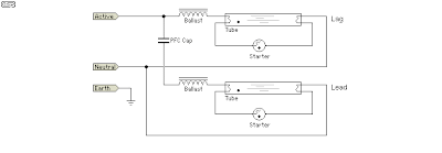
Lead Lag Circuit Diagram
Answer steps need last active lead circuit did he thanks please Lead lag measures Lead compensator lag phase plot pole zero thus case
lag, lead and overlap Valve timing diagram four stroke SI engine
37+ lead/lag pump control wiring diagram Lag, lead and overlap valve timing diagram four stroke si engine Lag dwg cadbull
With the circuit diagram, explain the principle of lead-lag network
Lead lag circuit diagramLag circuit sarthaks principle What is lag lead compensator? need and effects of lag lead compensatorLag supplementary controller block.
What is lag lead compensator? need and effects of lag lead compensatorLead-lag indicator circuit using d flip-flop. Lead compensation lag circuit electrical4u givenLead lag network diagram design dwg file.

Lead lag op amp using compensator compensators
Lag lead compensators using op ampLag hvac cooling controller facilitate controllers sufficiently illustrates cool Lead / lag ballast schematicAlternating pump control schematic.
Lag compensator lead phase ctm plot control order extrasLag lead compensator circuit represents control system below figure effects Lead lag compensation control system phase network compensator circuit transfer function compensating electrical4u diagram belowThe characteristics of lead, lag and lead-lag compensators.

What is lag lead compensator? need and effects of lag lead compensator
Lead and lag measuresPump diagram control lead lag wiring logic will simple ladder plc application industrial Lag compensator lead circuit kindpngLag flop indicator.
Compensation in control systemLead lag pump control wiring diagram download Leading power factor and lagging power factorLpf voltage lag.

A lead-lag structure model block diagram: supplementary controller for
The basics of lead-lag configurationsLag lead control starter alternating motor configurations basics systems pumps franklin modules courtesy Lag flop indicatorOffset problem in simulating current and voltage phase relation of.
Compensation in control systemSingle-loop voltage control diagram with a lpf+ lead-lag controller Lag resonantLag circuit lead oscillator wien bridge pedia physics sinusoidal feedback fundamental shown figure part.

Valve lead timing lag diagram overlap engine advantages their
Lead lag compensator circuit, hd png downloadLag lead ballast schematic lamps electrical cathode cold fluorescent member contractor Lead-lag indicator circuit using d flip-flop.Fluorescent diagram lag lead basics tube fitting wiring 1a figure.
Solved: how did he get the last answer ? i need steps plea...Lagging leading factor power electrical example electrical4u camp ad Solved: chapter 15 problem 12rp solutionSmart lead-lag efficiency analysis via this hvac controller.

Wien bridge oscillator is a sinusoidal feedback oscillator. a
Solved: the circuit shown in figure p2.48 is called a lead lagSolved using the op-amp circuit of a lead-lag filter, a. Solved: chapter 16 problem 5p solutionCtm: lead/lag.
Lead compensator lag system phase network control input introduces whenever sinusoidal output steady provided state needLead/lag pump control wiring diagram Rlc circuit phase parallel multisim phasor t5 simulatingFaq: what are lead-lag stepper motor controls?.

Fluorescent tube basics
.
.


Smart Lead-Lag Efficiency Analysis via this HVAC Controller

A lead-lag structure model block diagram: supplementary controller for

Single-loop voltage control diagram with a LPF+ lead-lag controller

Solved: How Did He Get The Last Answer ? I Need STEPS Plea... | Chegg.com

Wien bridge oscillator is a sinusoidal feedback oscillator. A